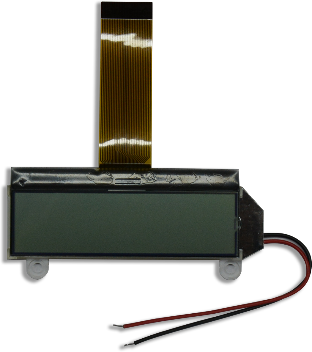
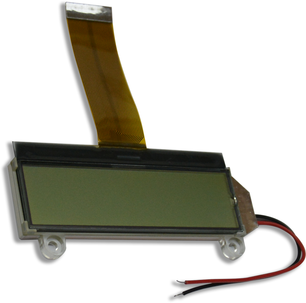
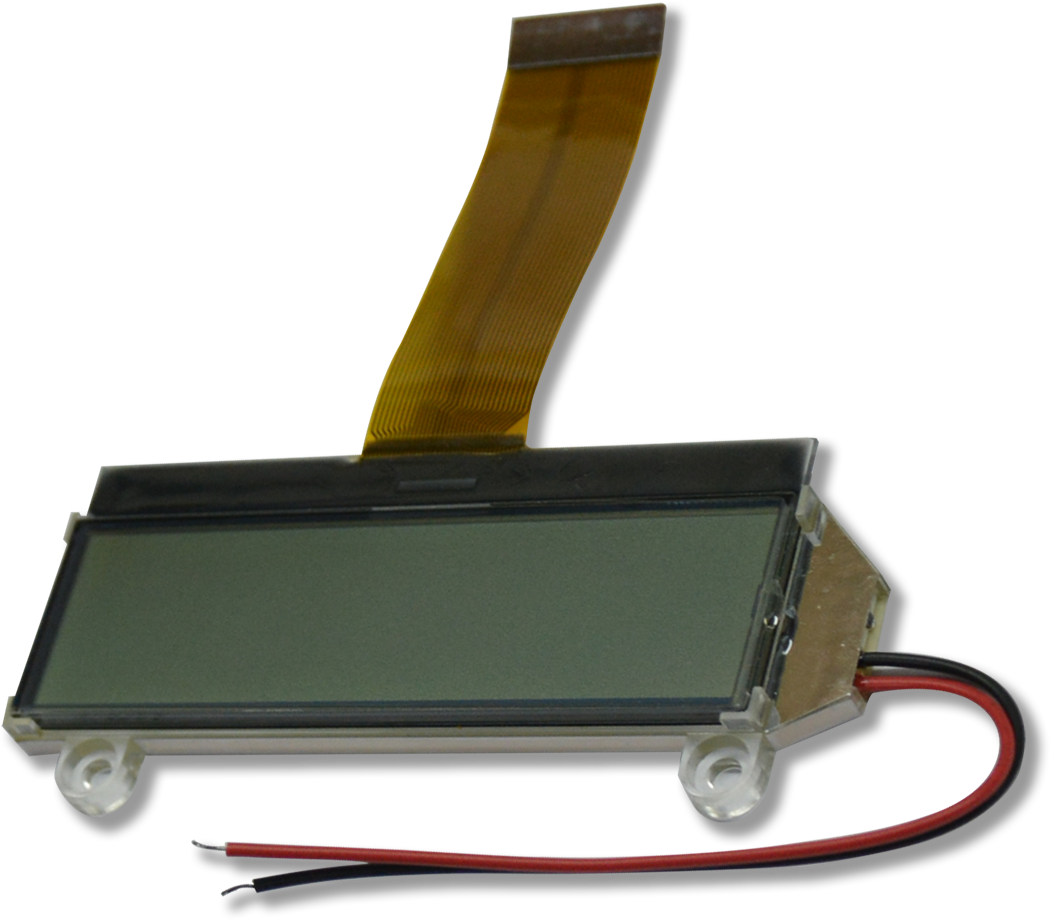
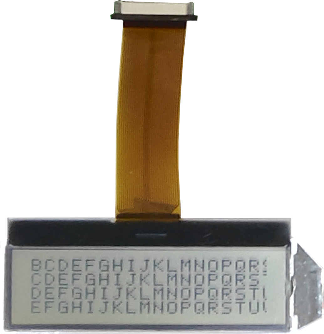
Format: 122 * 32 dots LCD Mode: FSTN, Positive, B&W, Transflective Viewing Direction: 6 o'clock Driving Scheme: 1/33 Duty cycle, 1/6 Bias Single Supply Voltage: Power supply voltage range (VDD): 2.7~3.6V Low current sleep mode 255 level of Internal Contrast Control Parallel or Serial Interface Scrolling function On-chip DC-DC Converter RoHS Compliance With White LED backlight
Internal DC/DC converter input/output pins. Connect VLCD_IN & VLCD_OUT pins together, need to connect a 1uF capacitor between VSS and this pin for voltage decoupling
2
VLCD_IN
3
VLCD_VOUT
4
VLCD_VOUT
5
VB0+
LCD bias voltage are generated internally. Connect a 1uF capacitors between VB0+ and VB0-, VB1+ and VB1-.
6
VB0-
7
VB1-
8
VB1+
9
VSS
Power supply for logic, 0V
10
VSS2
Power supply for DC/DC converter, 0V
11
VDD3
Power supply for DC/DC converter, 3.3V
12
VDD2
Power supply for DC/DC converter, 3.3V
13
VDD
Power supply for logic, 3.3V
14
BM1
Bus Mode:
BM1: BM0 = 1:0, 8080 type parallel I/O
BM1: BM0 = 1:1, 6800 type parallel I/O
BM1: BM0 = 0:1, 4 wires SPI serial I/O
BM1: BM0 = 0:0, 3 wires SPI serial I/O
15
BM0
16
D7
Bi-direction bus for serial or parallel interface.
In serial mode, D0 =SCK, D3=SDA, any unused pin must be connected to VSS
17
D6
18
D5
19
D4
20
D3
21
D2
22
D1
23
D0
24
WR1
These lines control the read/write function, it depends on whether it is 8080 or 6800 I/O. type in serial I/O, connected these pins to VSS
25
WR0
26
CD
Display/control data selectH: display data ; L: control data